 Rockriver.us
<
PREVIOUS PAGE
NEXT PAGE >>
More turbine install
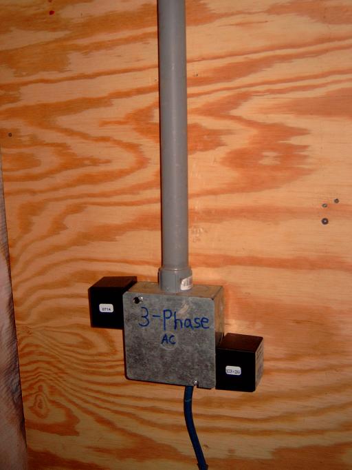
Here is a picture of where the 8-3 with ground UF underground cable
enters the power station. You see two more black lightning arrestors
mounted to the side of the 4" square metal box. Here I am preotecting
the 3
hotwires from the turbine again. I have 2 arrestors at the base of the
tower and two more here. This is to provide extra protection to the
ARE wind turbine controller and Outback FM80 wind controller which
contains sensitive
electronics. This equipment really needs to be protected. You see on
the bottom of the 4 inch box, there is a large wire coming out from the
bottom. This wire is a ground wire that I ran directly from the ground
rod outside the shack over to this box. This ground wire is
specifically for the ground wires of the lighning arrestors to connect
to. Normally you would just wire the lightning arrestors ground wires
to the normal ground that runs from the box over to the ground in the
controller and then to the outback FM80 and then to the FW-DC
ditribution panel's ground. To me this
does not make good sense. Why would you want to direct thigh voltage
lightning over to the grounds located in your controllers and
distribution equipment? Instead I think it is better to isolate the
lightning and direct it straight to the ground rod and bypass the
grounds in the equipment.
I used 1" pvc conduit from the top of this box, across the ceiling and
down to the ARE turbine controller box. The 4 inch box came with
only 1/2 inch
knockouts which accomodated the arrestors ok but I had to drill a 1
inch hole for the 1" pvc connector. I used a 1" in hole saw and a
cordless drill.
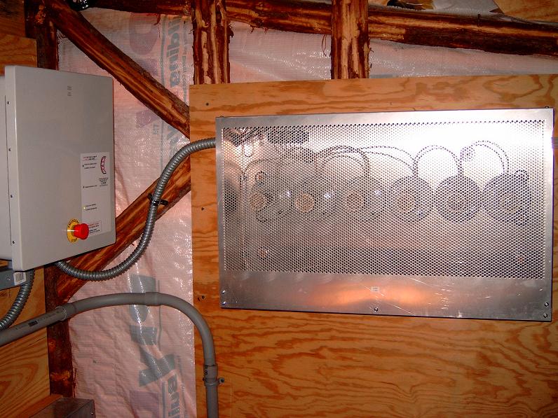
Below (left picture) is a picture of the ARE wind turbine
controller on the left and
the
diversion load on the right. Picture on the right does not show the
Outback FM80 wich would be mounted to the left of the ARE controller
because the FM80 did not come till much late in the
installation. Neither of these boxes is that heavy. I
just used some deck screws and washers to mount these to the 3/4 inch
plywood. The diversion load is made up of 6 light
sockets with these screw in heating elements. The screw in just like a
regular light bulb. I had to use another piece of plywood to mount the
diversion load
to. I also needed to pay special attention to how close the diversion
load was in relation to its surroundings. A.R.E recommends keeping it
away from anything 18 inches above, and 12 inches on all other sides.
Of course you would not have anything anywhere near the front of it
because these things can glow red hot and possibly cause a
fire!!
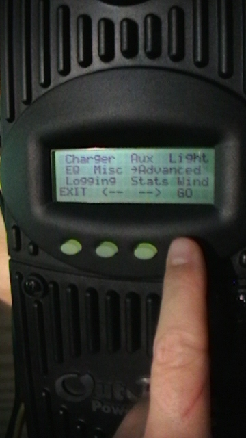
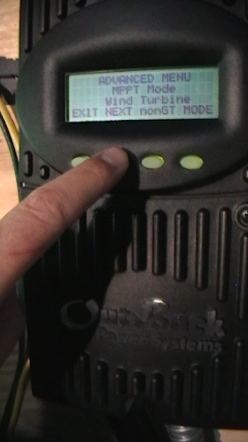
Below is a closer view of the worlds first (i believe) MPPT wind
turbine contoller (for battery charging)
made by
Outback for the ARE 110 - 2.5 kw wind turbine. Outback
has modified the FM80 and programmed it with a new mathematical
algorithm so that it will work with ARE's wind turbine. Its
called the Windtracker 80. If you go under the
advanced menu
then under MPPT mode, you can change the mode to wind turbine.
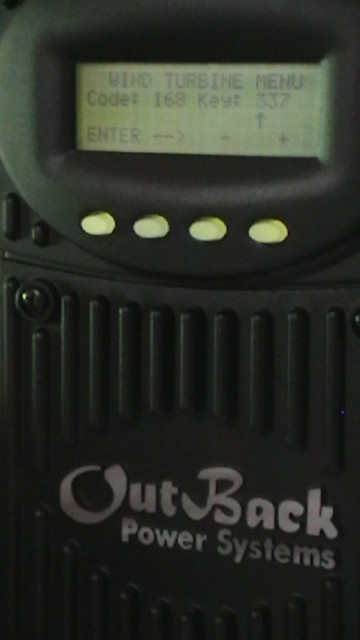
There is also a "Wind" menu which displays a code and a key. I found
out from ARE that this is the password protection in order to get into
the FM-80 and change the power curve information. This means that
theoretically , if you new the code then you could adjust the power
curve settings to work with a home Brew Axial flux wind turbine or any
other turbine for that matter. Outback and ARE are the only ones with
the passcode and will not give it out.
See below:
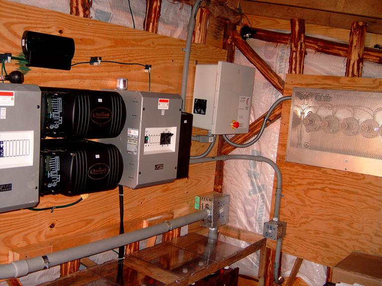
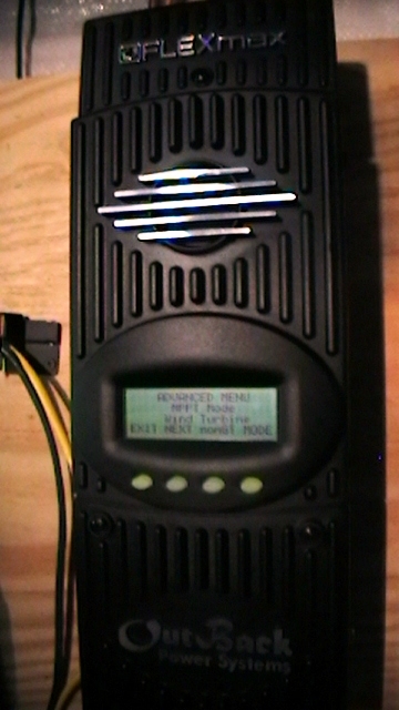
The picture below
on the left shows the modified FM80.
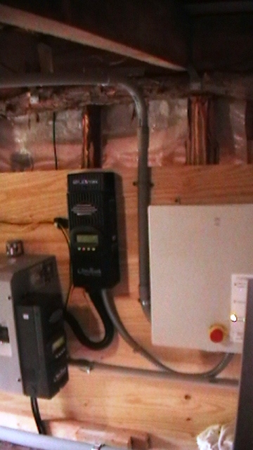
The picture below
on the right shows the Outback modified FM80 wind
controller mounted to the left of the ARE controller. I waited for this
controller for about a year an finally received it on September 18 2008.
ARE and Outback took a long time to work things out with testing,
equipment lableing, manuals, and testing of prototypes.They finally
pulled through. Before I got the outback,
my turbine (in 25 to 30 MPH winds) would only put out about
800 watts , wide open just before furling.
Now.. with the Outback, in estimated wind speeds of 15 to 20 MPH winds
, the Outback FM80 was showing readings
between 1000 to 1500 watts output ( I do not have an annenometer so I
am approximating the wind speed with the Beaufort scale techniques so
these are just ESTIMATIONS on wind speeds). This morning (sept 20 2008)
there
were
some pretty good gusts of wind and the turbine was putting out
sustained 2500 to 3000 watts ( at this time the wind turbine never
furled) . The ARE turbine is only rated for 2500
watts. Pretty impressive. I can't wait to see the output in some 25 to
30 mph winds. It is interesting that Outback Power has not made any
kind of announcement or anything about this new controller as of sept
2008. This is the
first MPPT wind controller anywhere in the world that I know of
thats made specifically for battery charging!!!!! and will
revolutionize the wind industry as we know it. I believe it will only
be a matter of time before other turbine manufacturers like Proven and
Bergy start working with Outback Power to make MPPT controllers for
their battery charging turbines as well.
Below is a shot of the inside of the ARE controller.
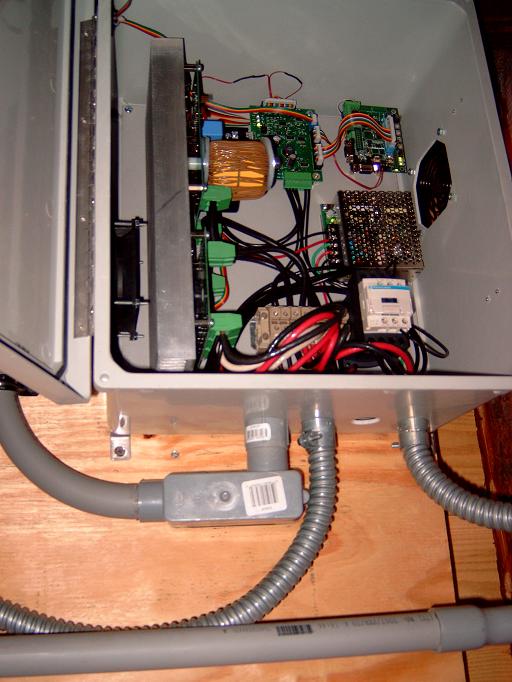
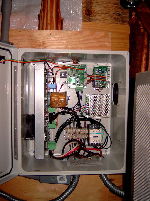
I used
1" rigid pvc for the conduit and #8 THHN wire between the 4 "
square box
(the one that I refered to earlier where the turbine wires enter the
building and had 2 lightning arrestors) and the bottom of the ARE
controller box transtioning into the the LB/ aka a sharp elbow with a
cover on it. There was a reason for the LB. ARE only puts conduit
knockouts in the bottom of their controller box. From the 4" metal box
I went out of the top, across the ceiling and down the left side of the
controller box and back up into the bottom of the controller box with
the LB. I personally think that having a knockout or two on the top of
the controller box would be an inprovement. ARE says you void the
warrantee if you drill new holes so I opted for the funky conduit run.
I
used 3/4 metal flexible conduit and # 8 THHN copper wires to run from
the ARE controller to
the diversion load. I used 3/4 metal flexible conduit and 6-3
thhn wire (I ran out of 8-3) from the ARE controller to the Outback
FM80 MPPT
wind turbine controller (A specially modified FM80- tentatively called
the
Windtracker 80). I used a plactic flex conduit that I found and have no
idea where it came from along with 6-3 to go from the FM-80 MPPT wind
controller to the FW-DC
distribution panel. I also needed to run #10 solid from the ARE
controller
mother board to the DC bussbar in the FW-DC to power up the
controller mother board and electronics. I ran the #10 in the same
conduit as the 6-3 thhn wire.
Initially , the ARE controller connected directly to the FW-DC. But,
after the FM80 finally came (after a year of waiting) I had to add the
FM80 in between the ARE controller and the FW-DC.
CLICK the manual link to download the A.R.E. 48V wind turbine manual.
NEXT PAGE >>